


Advantech BB-485CON
RS-232 to RS-485 Converter
 Eigenschaften
 Beschreibung
 Weitere Informationen
 Ähnliche Produkte
 Seite drucken
 Preis anfragen
 zeige Notizliste
 PDF
PDF
 Eigenschaften
 Beschreibung
 Weitere Informationen
 PDF
PDF
- Convert unbalanced, full-duplex RS-232 to balanced, full-duplex or half-duplex RS-485
- Extend RS-232 data signals up to 1.2 km (4,000 ft.)
- 240 kbps baud rate (typical)
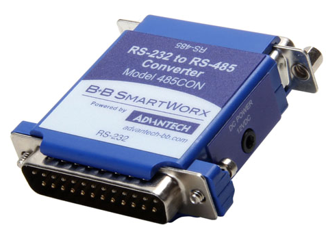
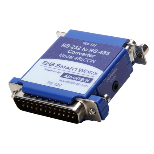
Model 485CON, RS-232 to RS-485 converter, converts unbalanced, full-duplex RS-232 signals to balanced, full-duplex or half-duplex RS-485 signals. RS-485 is an enhanced version of the RS-422 balanced line standard. It allows multiple drivers and receivers on a two-wire system.
The RS-232 port uses a male DB-25P type of connector with pins 2 (TD input) and 3 (RD output) supported. Protective Ground (pin 1) and Signal Ground (pin 7) are also connected. The RS-485 port uses a female DB-25S type of connector with Send Data outputs on pins 2 and 14, and Receive Data inputs on pins 5 and 17. Protective Ground (pin 1) and Signal Ground (pin 7) are connected through to the RS-232 connector.
The polarity of the two RS-485 lines must be correct. With no data being sent, the RS-232 line should be negative and the RS-485 A terminal should be negative with respect to the B terminal. If your equipment uses a + and - naming scheme, in most cases the A line will be connected to the - and the B line will be connected to the +. The RS-485 driver must be enabled when checking the polarity of the output of a RS-485 driver. On this connector, the RTS input (pin 4), on the RS-232 side must be raised to enable the RS-485 driver.
Figure 1 shows how to interconnect two RS-485 converters using two signal wires. The resistors Rt are optional, depending on the line length, baud rate, etc. The resistors should be about the impedance of the line used, which is normally about 120 Ohms each. Termination resistors are installed only at each end of the RS-485 multidrop network. RTS must be off (low or marking) to receive and on (high or spacing) to transmit. Both RTSs should not be on at the same time. Although you will not damage anything, the data sent will be garbled. If both RTS lines are off, the line may be floating and random data may appear on the outputs. Your protocol should allow for this if it can happen.
Up to 32 receivers can be driven by any one generator. This allows you to put together large systems with many drop points. The termination resistors should be located at approximately opposite ends of the system.
Proper operation of any RS-485 system requires the presence of a signal return path. The RS-485 Standard recommends that a third wire be used for this. For safety, a 100 Ohm resistor should be connected between pin 7 and the reference wire at every drop point. While it may be possible to interconnect signal grounds (pin 7s) directly, this is not recommended due to the danger of circulating currents possibly being present.
No wire type or maximum run length is listed in the RS-485 Standard. However, the RS-422 Standard, which is very similar, recommends 1200 meters (4000 feet) of number 24 AWG twisted-pair telephone cable with a shunt capacitance of 16 picofarads per foot.
SPECIFICATIONS
| SERIAL TECHNOLOGY | |
| Communication | 2-channel, RTS control |
| RS-232 Connector | DB25 male |
| RS-485 Connector | DB25 female |
| Data Rate | 240 kbps (typical); 120 kbps minimum |
| POWER | |
| Source Requirements | 12 VDC, 100 mA external power source |
| Connector | 2.5mm power jack |
| MEANTIME BEFORE FAILURE (MTBF) | |
| MTBF | 8800803 hours |
| MTBF Calc. Method | MIL 217F using Parts Count Reliability Prediction Method |
| APPROVALS / DIRECTIVES / STANDARDS | |
| FCC, CE | |
| Directives | 2014/30/EU - Electromagnetic Compatibility Directive (ECD) 2011-65/EU - Reduction of Hazardous Substances Directive (RoHS) 2012/19/EU - Waste Electrical and Electronic Equipment (WEEE) |
| Standards | EN 55032:2015 Class B - Electromagnetic Compatibility of Multimedia Equipment - Emission Requirments EN 55024:2010 - Information Technology Equipment - Immuity Characteristics - Limits and Methods of Measurement EN 61000-6-3:2007+A1:2011 - Generic Emission Standard for Residential, Commercial and Light-industrial Environments (Class B) EN 61000-6-2:2005 - Generic Immunity Standard for Industrial Environment |
SPECIFICATIONS
| Available Module | |||
| MODEL NUMBER | RS-232 CONNECTOR | RS-485 CONNECTOR | OUTPUT SIGNALS |
| BB-485CON | DB25 Male | DB25 Female | Full- or half-duplex RS-485 |
 Kunden, die diesen Artikel gesehen haben, sahen auch